| - MRR TUTORIALS - BENCHWORK - OPEN GRID | SITE MAP |
Open-Grid Benchwork for Model Railroads
Open Grid benchwork
The benchwork forms the foundation of every model railroad. No matter how realistic the scenery, detailed the rolling stock, or advanced the control system may be, everything ultimately depends on a stable and well-planned framework. One of the most popular construction methods among model railroaders is open-grid benchwork. It is strong, lightweight, easy to build, and highly adaptable to different track plans and landscape forms.
What Is Open-Grid Benchwork?
Open-grid benchwork consists of a series of interconnected wooden frames forming a grid-like structure. The framework is typically built from plywood strips assembled into rectangular or irregularly shaped boxes. Rather than supporting a full sheet of plywood across the entire layout, only the areas needed to support the track and scenery are built. This creates a lightweight construction while still providing excellent strength. An easy way to visualize open-grid construction is to think of it as a collection of wooden boxes connected together. Each box can be square, rectangular, triangular, or any shape required by the track plan. When joined together they form a rigid and stable foundation for the entire railroad.

Open Grid benchwork dividable in three segments with integrated drawers, removable and adjustable legs.
Advantages of Open-Grid Construction
There are several reasons why open-grid benchwork has become one of the most widely used construction methods. The open spaces between the beams provide excellent access for wiring, turnout motors, lighting and electronics. It also becomes easier to reach hidden tracks and tunnels from below. Another advantage is flexibility. Since the framework only supports selected areas, hills, valleys, rivers and other landscape features can be created without having to cut large holes through a solid tabletop. The result is a structure that is both lighter and easier to modify than many traditional tabletop designs.
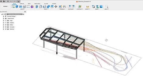
Here´s the Wintrack trackplan inside the CAD-software helping me to make optimal beam placement for the Open Frame benchwork.
Planning the Benchwork
Before cutting the first piece of wood, the track plan should be finalized. Modern track planning software makes this process significantly easier.
Once the track plan has been completed, it can be exported as an image and imported into a CAD program. This allows the framework to be designed around the track plan rather than the other way around.
One important benefit is that turnout motors, signal mechanisms and other sub-panel mounted equipment can be considered during the design phase. Cross members can be positioned so they do not
interfere with switch motors or future maintenance work.
The framework should also include access openings large enough for a person to reach hidden track areas. Derailments, track cleaning and maintenance will eventually be required, and planning for access now can prevent frustration later.
Materials and Construction
Plywood is an excellent material for open-grid benchwork. For long beams and outer frame members, 16 mm spruce plywood provides excellent rigidity.
Cross members can often be made from 12 mm plywood to save both weight and material costs. The benchwork is assembled using wood glue and screws.
A flat surface helps ensure that all sections remain square during assembly. The legs are commonly made from 45 x 45 mm timber. While simple in appearance, this arrangement
provides excellent stability when properly braced by the framework itself.
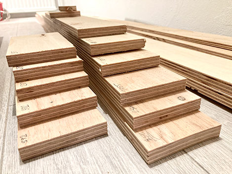
Using 16mm for the center and long sides and 12mm thick Plywood for the crossmembers provides excellent long term stability.
Adjustable Legs
Very few floors are perfectly level. For this reason it is highly recommended to install adjustable feet at the bottom of each leg.
These inexpensive fittings allow the layout height to be fine-tuned after installation. Adjustable feet become especially valuable on larger layouts where even small floor
irregularities can cause noticeable height differences across the railroad. They also simplify the assembly of layouts built in multiple sections. Suitable height of the benchwork is 900-1000mm. That will allow for easy access under the layout and still reasonable height on landscape surface even for kids.
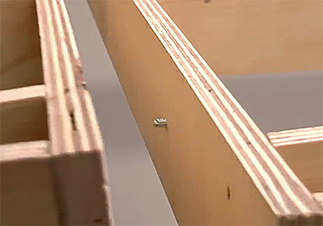
Guide pins ensure perfect alignment when re-assembled.
Designing for Future Relocation
Many model railroaders eventually face the challenge of moving their layout. Unfortunately, countless layouts have been demolished simply because they were not designed to be moved.
By planning for relocation from the beginning, much of the railroad can often be preserved. The first step is determining the maximum size of each section.
Consider door openings, hallways, staircases, windows and transportation requirements. A section that cannot leave the room will eventually become a problem.
Once these limitations are known, division lines can be incorporated into the track plan and framework design.
Guide Pins and Alignment Systems
A movable layout requires accurate alignment whenever sections are reassembled. Guide pins provide a simple and effective solution.
Mounted in the end plates of adjoining sections, they ensure that every section returns to exactly the same position each time it is assembled. Bolts are then used to lock the sections together.
When properly installed, guide pins provide excellent alignment for both benchwork and trackwork. This greatly simplifies future moves, maintenance and transportation.
Marking the division lines on the framework also helps identify where the layout should be separated if relocation becomes necessary.
Building the Subroadbed
Once the framework is complete, the subroadbed can be installed. A common approach is to use 12 mm plywood cut to follow the shape of the track plan.
The subroadbed should generally extend 40 to 50 mm beyond the outer edges of the track. This extra width provides room for scenery, fences, utility poles and other details alongside the railway.
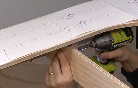
Modern track planning software often allows the track plan to be printed in full size. These paper templates can be taped together and placed directly on the plywood, making it easy to transfer the track alignment accurately.
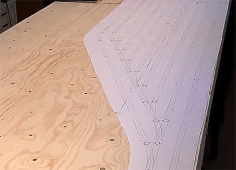
Track plan printed in full size. These paper templates is taped together and placed directly on the plywood
Grades and Risers
Where tracks need to climb or descend, risers are used to support the subroadbed. The height of each riser is determined by the desired grade.
Risers are typically cut from plywood and attached directly to the framework below. It is often difficult to predict every riser location during the design phase.
Additional cross members are frequently added during construction to ensure proper support. Particular attention should be paid near section joints.
Adding extra support close to the start of a grade helps prevent abrupt changes in track elevation.
Installing risers elevates the roadbed allowing landscape to be lower than the tracks
Roadbed Installation
Many model railroaders install cork or foam roadbed on top of the plywood subroadbed. Foam products provide good sound insulation and are easy to shape.
Cork remains a popular alternative due to its durability and consistent dimensions. The roadbed is normally attached using white glue or flexible construction adhesive,
depending on the material selected. Once complete, the layout is ready for track laying.
Conclusion
Open-grid benchwork combines strength, flexibility and accessibility in a way few other construction methods can match. By planning the framework around the track plan,
using adjustable legs, providing maintenance access and incorporating guide pins for future relocation, it is possible to create a foundation that will serve the railroad for decades.
A well-built benchwork may never be seen once the scenery is complete, but it remains one of the most important investments in the entire model railroad project.