| - MRR TUTORIALS - CONTROL - CONTROL BOARD |
An old style control board?
Why should you build an old-school control board, when you already have a touch screen with both turnouts and other assoseries, That must be completely unnecessary, or? The electric switches on a smaller model railroads can easily be serviced with Märklin type 7072 switch box. For larger layouts with more turnouts, decoupling tracks, staging or fiddling yards, it will be necessary to build a simple control board to get an overview of all functions. If the Model Railroad is larger, it is convenient to have a control board at each station. If you run computerized and have the turnouts in your Smartphone, it is still better with control board, because then you can control the locomotive with the phone, while the turnouts are operated simply and smartly with the other hand.Control of the various functions of the model railway is done with rocker and pushbutton switches. The toggle switches for turnout changes have a flat arm, so it is easy to both feel and see which way to operate. If color marking is desired, this is done simply by painting the top of the rocker with, for example, Humbrol's colors. Other features have a round arm, so they can be easily separated. Furthermore, these always latch one way or the other, which makes it easy to see which position is selected.
What features are needed?
The following features are useful for collecting on the tram board:
- Toggle switches for turnout changes
- Toggles for switching on / off the current for installation grooves.
- Toggles to manually change signals from drive to stop and vice versa.
- Pushbutton switch for actuating the decoupling rails.
- Toggles for switching on / off the power for lighting in houses and on platforms.
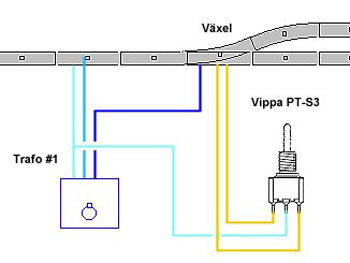
Så här ansluts vippan till transformator och växel.
Toggle switches for turnout changes
A three-position spring-return-to-center rocker type is used for the control of turnouts. The rocker is OFF in the middle position. When the rocker is moved one way or the other, the electrical circuit between the transformer socket (0) and one blue cable of the turnout unit is closed. The turnout position is changed.
Toggle switches has three solder connections. Connect one cable from the transformer socket (0) to the center contact and the two blue cables of the switch on the other two contacts (see wiring diagram here next)
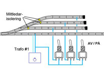
Toggle switches for staging tracks
A 2-position rocker type with two fixed positions is used for the control staging tracks. It has two fixed positions: Power off / Power on. When the rocker is moved in one or the other direction, the electrical circuit between the transformer socket (B) and the central conductor of the supply rail is closed or broken.
Connect a cable from the transformer socket (B) to the center socket and the red cable from the feed rail in the set-up groove to one of the other two solder connections (see wiring diagram here next).
Example of wiring the toggles
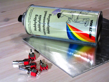
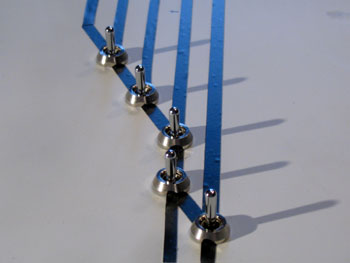
Aluminum control board with taped track layout
A 1.5mm aluminum sheet costs a fifty on Jula, or Clas Ohlson. With the help of a spray can from Biltema for you can paint it neat gray, or white. You can also find the terminal block on Biltema, as well as solder tin and soldering iron.
Sketch the track plan in pencil on the lacquered plate and drill 6mm holes for the lashes and 3mm holes for any LEDs. Using a matte knife, ordinary electrical tape is cut to a suitable width and taped to the lacquered board. Cut away the tape where it covers the holes and mount the toggle switches and LEDs.
.
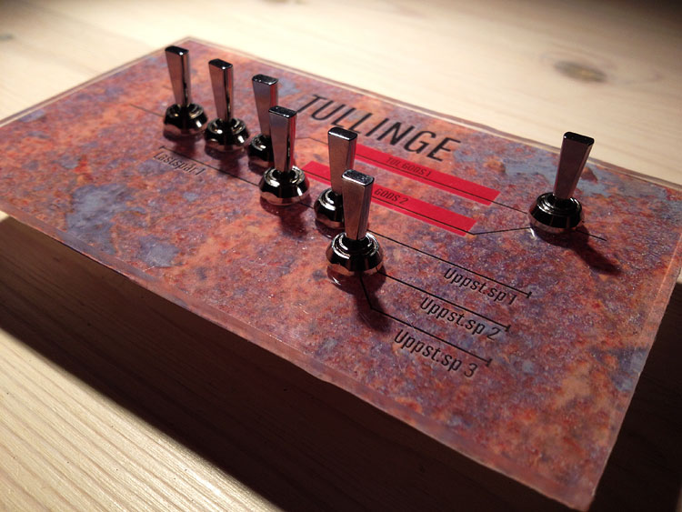
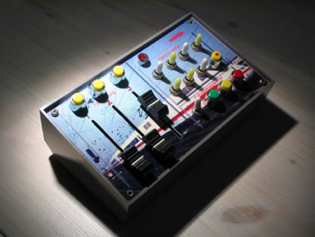
Control board in aluminum and printed overlay on glossy photo paper
If you draw your track plan using a computer program, such as Wintrack, you can make a really stylish and functional track board using a print on photo paper, or on Overhead plastic, as shown below. Start by cutting out the board in 4mm plywood and sanding its top evenly. Irregularities can advantageously be cracked and sanded away. Print the tracer board on inkjet or laser printers on photo paper.
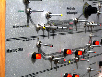
Control board in transparent PVC with printed track layout
If you draw your track plan using a computer program, such as Wintrack, you can make a really stylish and functional track board using a print on photo paper, or on Overhead plastic, as shown below. Start by cutting out the board in 4mm plywood and sanding its top evenly. Irregularities can advantageously be cracked and sanded away. Print the tracer board on inkjet or laser printers on photo paper.
Protective varnish necessary Glue the print to the plywood board using a thin, stretched layer of wood glue. Let dry. Drill 6mm holes for the lashes and 3mm for any LEDs.
|
|
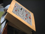
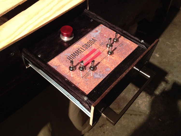
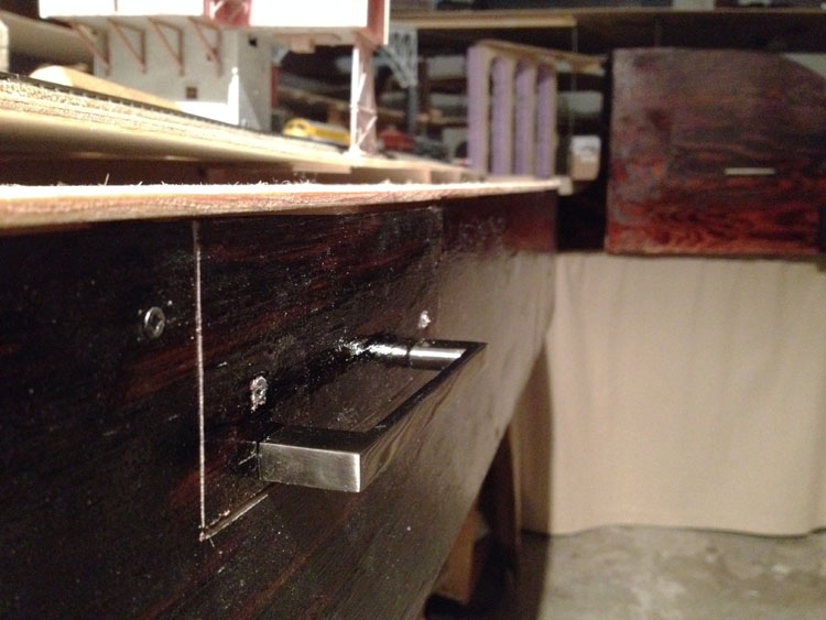
Control board in a drawer |
||
|