| - MRR TUTORIALS - CONTROL - ANALOG AC INDEX - TURNOUTS |
How to Connect Märklin Electric Turnouts
The Märklin 5100/5200 metal track series includes several turnouts that can be remotely operated. Remote control is performed using the Märklin 7072 control box, or preferably with toggle switches mounted in a custom-built track diagram panel. Märklin electric turnouts contain a built-in solenoid that moves the switch points. A solenoid is an electromagnet with a movable iron core.The motor of the turnout (the solenoid) has three connections:
Yellow wire connected directly to the transformer’s yellow terminal marked “L”.
Blue wire with red connector connected to the red terminal on the control box.
Blue wire with green connector connected to the green terminal on the control box.
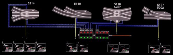
The lamp is connected to the track rails (“0”)
The yellow wire is also connected to the turnout’s built-in lamp, which illuminates the semaphore signal. The other terminal of the lamp is connected directly to the track rails and thereby to the transformer terminal marked “0”.
This is important to be aware of if the layout is later converted to digital train operation. It is namely the only electrical connection between the digital track power and the AC transformer.
Märklin control boxes for turnouts:
The older blue model, article 7072
The newer white model, article 70720
Both have the same function.

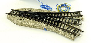
Three-Way Turnout (Article 5214)
The three-way turnout has dual solenoids and therefore uses four blue wires and one yellow wire. Two of the blue wires are connected together to control the straight route. The remaining two control the right-hand and left-hand diverging routes respectively. Switching directly from the left-hand route to the right-hand route, or vice versa, must always pass through the straight position in order for the switch points to align correctly.