| - MRR TUTORIALS - CONTROL - ANALOG AC INDEX - MULTI-TRAIN |
Wiring for Multi-train operation
Only one train per isolated track sectionMärklin’s electrical system for operating with alternating current (AC) consists of two components: a variable transformer and a feeder track. The feeder track has two connected wires — one brown and one red — which are connected directly to the color-coded terminals (brown and red) on the transformer. Brown is the electrical ground/common return and is often marked “0”. Red is the electrical phase/output and is marked “B”.
|
|
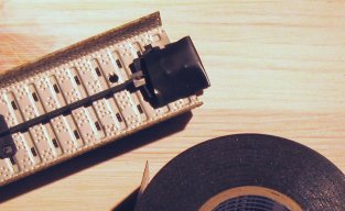
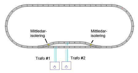
Multi-Train Operation with Transformers When a layout is small and perhaps only consists of a starter set, it is usually sufficient to let a single locomotive handle both freight and passenger traffic. However, it does not take long before additional locomotives are added, and then the layout must be divided into several separate electrical sections, each operated by its own transformer. Isolation Between Sections The easiest way to isolate different sections is to place a small piece of electrical tape over the center conductor contact. See illustration. Märklin also manufactures special center conductor insulators for a more professional solution. The article number is 5022, although I am uncertain whether it is still available for purchase today.
|
Connecting Operating Power to Each New Section Each new section requires an additional transformer and a feeder track for operating power. The straight feeder track is called 5111 and the curved version is called 5103. However, it is extremely easy to make your own feeder tracks by soldering wires to any piece of track. Checking Polarity Repeat this check between all transformers.
|
 |
|||
I have connected all my transformers to the same power strip. When I want to operate the layout, I simply plug in the power strip and then know that all transformers are connected correctly every time, since I never unplug them individually.
|
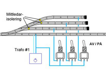 |
Spur tracks, storage tracks for train sets, and tracks inside locomotive sheds do not require their own transformer, but they must be possible to switch on and off from the nearest section/transformer. This is most easily accomplished using a toggle switch. The wiring method is shown in the illustration beside this text. The toggle switches are preferably mounted in a track diagram panel or control panel next to the transformers so they are easily accessible during operation. |