| - STARTSIDAN - STYRNING - ANALOG AC VÄXELSTRÖM- KOPPLA KÖRSTRÖM |
Wiring the track power for Märklin AC systems
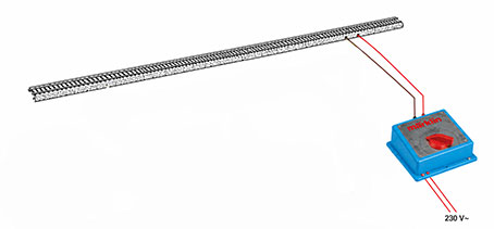
Simple! Two wires is all that neededMärklin’s electrical system for operating with alternating current (AC) consists of two components: a variable transformer and a feeder track. The feeder track has two connected wires — one brown and one red — which are connected directly to the color-coded terminals (brown and red) on the transformer. Brown is the electrical ground/common return and is often marked “0”. Red is the electrical phase/output and is marked “B”.
The Transformer
Märklin’s transformer converts 230V AC from the mains power supply into a suitable alternating voltage for the model railroad.
The transformer generally has 3–4 terminals:
- Brown is the electrical ground/common return and is marked “0”.
- Red provides 0–16V AC and is marked “B”.
- Yellow always provides 16V AC and is marked “L”
Feeder Track
The feeder track (article 5131) is just a standard piece of track with two connected wires:
- Brown ( − , “0”) is connected to the rails
- Red ( + , “B”) is connected to the center conductor
This makes it very easy to create additional feeder tracks yourself. All that is needed is wire, solder and a soldering iron.
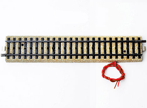
Some tracks also have a small capacitor connected underneath. This capacitor is not necessary and can be omitted. Its purpose is to reduce the electrical interference generated by the locomotives as they run on the rails.
If the layout is later converted to digital operation, these capacitors must be removed. It is therefore often preferable to remove them from the beginning and avoid having to tear up the track on the layout at a later stage.