| - MRR TUTORIALS - CONTROL - ANALOG AC INDEX - SIGNALS |
Marklins analog signal system 7000
Unfortunately, I have always felt that Märklin’s signal system has been complicated to connect and operate. That is a pity, because only much later did I realize how much practical use and enjoyment I could actually have gained from installing a few signals on my first three layouts.
All of this at a tiny cost of just a few dollars each and with only a few simple steps required for installation. That is why I am now writing this guide. For those building a larger layout — more than 20 turnouts and simultaneous operation of more than four locomotives — I instead recommend investing directly in a digital system with PC control.
Three Types of Signals in the 7000 Series The main signal provides information about proceed/stop, route setting and permitted speed. The shunting/blocking signal is normally used to control departures from station areas or industrial sidings. |
 |
|||
|
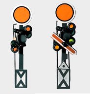
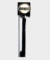
Distant Signals on a Model Railroad Distant signals on a model railroad are mainly decorative. They have no real operational function, since the track sections are usually very short. As a result, the distant signals are often placed only a few pieces of track before the main signal. If you choose not to install them initially, they can easily be added to the layout later. In most cases, they are not something you need from the beginning. The distant signals in Märklin’s 7000 signal system have the following item numbers:
|
|
|
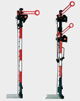
Main Signals on a Model Railroad It is the main signals that form the core of your signal system. The main signals contain a built-in bistable relay, which switches the track power on and off for the track section located in front of the signal. When the signal shows green, or the semaphore arm is raised, power is supplied to the track. When the signal shows red, or the semaphore arm is lowered, the power is disconnected and the train stops in front of the signal. The main signals in Märklin’s 7000 signal system have the following item numbers: Semaphore signals: 7039, 7040
|
|
Shunting signals are normally used to prevent switching locomotives from accidentally entering a main line from station areas or industrial sidings. The shunting signals contain a built-in bistable relay that switches the track power on and off for the track section located in front of the signal. The shunting signals in Märklin’s 7000 signal system have the following article numbers: Semaphore signal: 7042
|
|||
Wiring the analogue Marklin signals Märklin signals are connected in essentially the same way as the turnouts. This means that the signal’s yellow wire with yellow connector is connected directly to the transformer’s yellow terminal. The signals have three blue wires: one with a red connector, one with a green connector and one with an orange connector. By momentarily connecting either the red or green connector to the transformer terminal marked “0”, the signal is set to “STOP” or “PROCEED” respectively.
|
Manual signal control can be suitable in locations where you want to manually authorize train movements. The signal’s blue wires — the one with the red connector and the one with the green connector — are connected to the Märklin 7072 control box. The red wires with their contact tabs are connected to the track center conductor at two rail joints: partly before the signal where track power is present, and partly after the signal in the isolated track section. The side terminal of the control box is connected to the transformer terminal marked “0”. By pressing either the red or green button on the control box, the signal is switched to “STOP” or “PROCEED”. |
|
|||
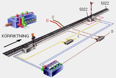
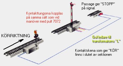
Automatic signal control can, for example, be suitable along main lines where you want to prevent one train from catching up with another train. The signal’s blue wires — the one with the red connector and the one with the green connector — are connected to separate 5146 contact tracks. The first contact track, “STOP”, is placed immediately after the isolated section. The second contact track, “PROCEED”, is positioned at the end of the section.
The red wires with their contact tabs are connected to the track center conductor at two rail joints: partly before the signal where track power is present, and partly after the signal in the isolated track section. The yellow wire is connected directly to the transformer terminal marked “L”.
|
|
|||